B24 Consolidated Liberator


111 OTU B24 Liberators at Windsor Field, Nassau, LO is B.III BZ762 and MA is GR.V BZ810
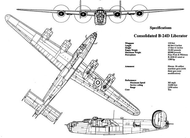
The Consolidated B-24 Liberator is an American Heavy Bomber, designed by Consolidated Aircraft of San Diego, California. It was known within the Company as the Model 32, and some initial Models were laid down as Export Models designated as various LB-30′s, in the Land Bomber design category. The B-24 was used in WW2 by every Branch of the American Armed Forces, as well as by several Allied Air Forces & Navies, attaining a distinguished War Record with its Operations in the Western European, Pacific, Mediterranean & China-Burma-India Theatres and in Anti-Submarine Warfare. The Liberator carried a Crew of up to 10. The Pilot & Co-pilot sat alongside each other in a well-glazed Cockpit. The Navigator & Bombardier, who could also double as a Nose or ‘Wiggly Ear’ Gunner (Guns mounted in the Sides of the Aircraft Nose), sat in the Nose, fronted on the pre-B-24H models with a well-framed “Greenhouse” Nose with some 24 glazed panels in total, with 2 flexible Ball-mounts built into it for forward defensive Firepower using .30 caliber (7.62mm) Browning M1919 Machine Guns.
Anatomy of the B-24 Liberator
The Liberator design incorporated advances in Aerodynamics & Technology that were some 5 years more advanced than the Flying Fortress. The most radical feature was perhaps the efficient, high aspect ratio Davis Wing, which promised to bestow the Liberator with a low-drag, high-lift performance. When this Wing was married to the box-like Liberator Fuselage and successive versions were required to carry ever increasing weights of Military Equipment, the performance promise of the early design became a distant memory. The clever design of the B-24s deep Fuselage & Twin Bomb Bays meant extra Fuel could be carried in one Bay and a useful load of Bombs in the other, giving the Aircraft exceptional range for its time.

Fuselage
The many different versions of the B-24 varied a great deal in the detail of their internal equipment. The description that follows is typical for a late production B-24J Series, any significant variations with other versions are highlighted. The deep oval Fuselage is of all-metal, stressed skin and is defined as a semi-monocoque design. Running longitudinally are rolled aluminium Z-section Stringers spaced approximately 6in apart, but with reduced spacing where greater strength is required in areas such as the Bomb Bays. Heavy Section Longerons carry Loads through the Bomb Bays and other Fuselage openings. Circumferential Frames or Stations are of aluminium lipped-channel and are notched to pass over the Stringers and the spacing between stations is approximately 1ft 6in. Numbering is from 0 which is a Datum point in the extreme Nose to the Datum point 10.0 at the Tail. Compartments are separated by stations with whole numbers with intermediate stations numbered 0.1, 0.2 etc.

B24 Tail Gunner
There are 5 Structural Bulkheads, – forward of the Flight Deck, aft of the Flight Deck, between the 2 Bomb-Bays, aft of the Rear Bomb-Bay and at the end of the Rear Compartment just forward of the Rear Turret; these serve to separate different Fuselage Compartments as well as to add strength to the Structure.

The Alclad aluminium skin is attached to the Stringers & Stations by rivets to provide the stressed skin element of the Structure. The design ensures that Stresses are evenly dispersed throughout the Airframe rather than being concentrated at a few points.
Nose Compartment
This Section, between the Nose & Station 1.0 contains the working area for the Bombardier & Navigator. The Bombardier also manned the Nose Turret, usually either a Consolidated or Emerson Type. The Consolidated Turret is a hydraulically powered unit, which is plumbed into the Aircraft’s main Hydraulic System, while the Emerson type A-15 is an Electrically operated Turret taking its power from the main 24-volt system. It is entered via 2 Doors; the Gunner is seated with his feet resting in the Turret Bowl. 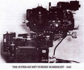 Below the Turret is the Norden Bomb-Sight looking through the Optical Glass Panel. To the Bombardier’s left is the Bomb Release Panel, controlling the release sequence of the Bombs and below it, the Intervalometer controls the timing of the Bomb Release. Just behind this sits the Actuating Levers for opening the Bomb Doors and for Emergency Salvo of the Bombs. To his right, is the Drift Meter used to measure the effect of Drift on the Aircraft over the Ground. In B-24 D & E Aircraft the front of the compartment consisted of a multi-panelled Plexiglass Nose containing 2 or sometimes 3 Machine Guns. Immediately behind the Bombardier is the Navigator’s Table & Swivel Seat, the Navigator sitting facing backwards at his Table, on the Bulkhead in front of him are his Flux Gate Compass Indicators and other Navigational Instruments. At the Rear of the Compartment on the right-hand side is the Entrance to the Crawl Way running underneath the Flight Deck. This leads past the Nose Wheel and gives the Crew access to the Bomb Bay and the rest of the Aircraft.
Flight Deck
The Flight Deck is positioned above the Nose Wheel, and behind the Nose Compartment between Stations 1.0 & 4.1. At the Front, the Pilots sit in their Compartment with Seats & Controls for the Pilot on the left and Co-Pilot on the right. Immediately behind them is the Martin Upper Turret normally manned by the Flight Engineer. To the right of the Compartment, behind the Co-Pilot, the Radio Operator has a Work Table & Seat. The Pilots each have Linked Control Wheels which have a push & pull action into and out of the Instrument Panel to control the Elevators. Ailerons are operated by rotating the Wheel in the normal sense. On the floor in front of each Pilot are 2 Pairs of linked Rudder Pedals each with Toe Brakes incorporated.
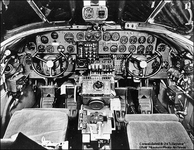
In front of the Pilot’s Panel are the Main Flight Instruments, namely the Directional Gyro, Gyro Horizon, Rate of Climb Indicator, Airspeed Indicator, Turn & Bank & Altimeter. There are also a Pilot Directional Indicator, Suction Gauge, Hydraulic Pressure Gauge, & Brake Pressure Gauges. On the Sidewall to the Pilot’s left are Controls for his Oxygen & Interphone Connections. In front of the Co-Pilot are Gauges related to Engine Management for Fuel Pressure, Cylinder Head Temperature, Oil Pressure, Oil Temperature & Carburettor Air Temperature. Additionally, he has Gauges & Switches for the Anti-icer & De-icer Systems. To the left of his Control Wheel, is an Electrical Switch Panel containing switches to operate the Fuel Booster Pumps, Engine Starters, Oil Dilution & Fuel Priming System. On his right Sidewall, the Co-Pilot has further switches for the Heater & Defroster Circuits, Main Batteries and for the Magnetos. Across the centre of the Instrument Panel, between the 2 Pilots the Instruments relating to the Power developed by the Engines are grouped, the Manifold Pressure Gauges & Tachometers. All Engine Instruments are of the Dual Dial Design, requiring one Instrument per pair of Engines. Just below these, almost in the centre of the Panel the Square Control Box for the Automatic Pilot is situated. Positioned between the Pilots the Central Control Stand or Pedestal contains Engine & Flight Controls and more Electrical switches. At the Top, the forward part of the Pedestal is the Turbo Boost Selector Knob. Earlier B-24s with the Mechanical Boost Control had 4 Levers in place of this Control for adjusting the Turbos on each Engine individually. To the right of this are the 4 Throttle Levers and next to them, 4 similar Levers for the Mixture Control. Further forward, switches controlling Propeller Pitch, Intercooler Shutters, Cowl Flaps & Exterior Lighting. The Aileron Trim Control Knob is in the centre of the top of the Pedestal, within reach of both Pilots, as is the Rudder Trim Wheel, on the Front face of the Stand. Down on the left side is the Elevator Control Wheel, only reachable by the Pilot. At the Base of the Pedestal on the Pilot’s side is the Landing Gear Control Lever and on the Co-Pilot’s side the Lever for raising and lowering the Wing Flaps.

B24 Upper Gunner
1900 B24s were supplied to the RAF. Liberators were used by RAF Bomber Squadrons in the Middle East, and from January 1944 became the principal RAF Strategic Bomber in the Far East. Liberators were also deployed by RAF Coastal Command, playing a key role in the War against Germany’s Submarine Fleet. Liberators also saw Service as Transports; indeed, (AL504 Commando) became the personal Aircraft of Prime Minister Winston Churchill for a short time.